
One of the main causes of RF (radio frequency) interference is intermodulation products created by our own wireless equipment. In this piece, I will outline some of the common setup and handling errors that contribute to this problem.
First up is increased noise floor and intermodulation (intermod or IM) products due to transmitters being in very close proximity. You might not encounter this if you work with a single band and just put mics up on stands every day.
But at festivals, broadcast events, churches, and theatrical productions, there are situations where a number of active transmitters (i.e., microphones, belt packs) must be marshaled somewhere and handed out to talent at various intervals.
Figures 1A, 1B, and 1C show the effects of handling six handheld wireless microphones in different ways. (All data charted with an Invisible Waves X PC-based RF spectrum analyzer from Kaltman Creations.)
In Figure 1A, they’re on stands about 4 feet apart. In Figure 1B, they’re lying side-by-side on the fader bay of a console. In Figure 1C, they’re back on stands, with the red trace showing IM and increased noise floor (the “after” result).
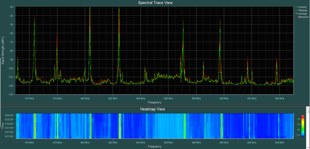
Figure 1A
We can clearly see that it goes from a very clean RF spectrum to a very noisy RF spectrum and then back again. There are several ways to deal with this common problem:
—If laying the transmitters out on a table (or a road case), arrange them so that the antennas are pointing in opposite directions for each mic (one up, one down, etc.).
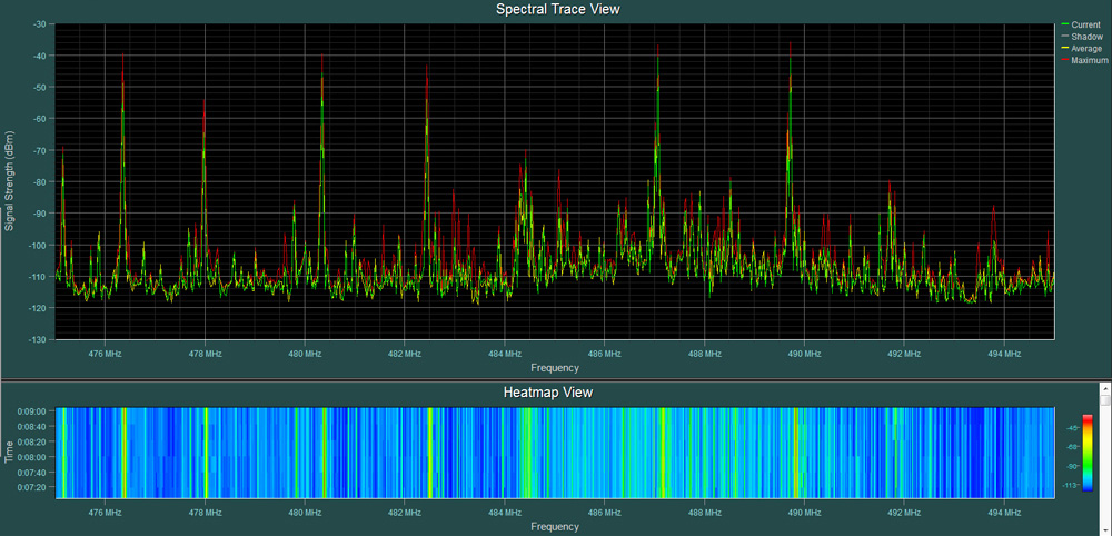
Figure 1B
—If you encounter this regularly, invest in some aluminum loaf pans and place the transmitters in them, with the antenna end in each pan.
—Monitor engineers who keep their lead vocal mic and the spare on the console should place them either windscreen-to-windscreen or both facing the same way, so the antenna end of one faces the windscreen of the next.
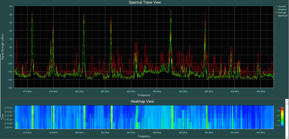
Figure 1C
The same problem occurs with in-ear monitoring systems because, out of necessity, there are usually several transmitters near each other. The trick here is to use antenna combiners with varying degrees of intermod suppression built into them.
Figures 2A and 2B show a rack of six IEM systems with whip antennas fitted (Figure 2A) and then routed through an antenna combiner (Figure 2B). Note that Figure 2B is also the “after” shot and clearly shows all the intermod products in red.
Figure 2A
In this case, five of the IEM frequencies shown are on top of a weak DTV (digital television) channel, channel 34. This accounts for the 6 MHz wide “hump” that the five channels are sitting on. I didn’t program or coordinate any of the frequencies shown in these plots but merely grabbed a couple of racks that had come back from a show and analyzed what was already programmed.
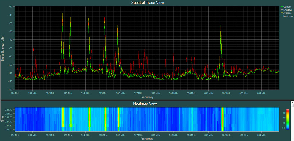
Figure 2B
Careful Arrangement
Antenna placement is key – in particular, keeping transmit (Tx) and receive (Rx) antennas separated is important. This is because a Tx antenna near an Rx antenna will desensitize it. This works in much the same way as the human eye or ear: if you’re trying to look at a dim object like a distant star, and there’s a bright light shining in your eyes, the bright light desensitizes them. So, an IEM antenna right next to a mic antenna is going to make that antenna less sensitive to a mic on the far side of the stage.
What to do? Assuming you’re using cardioid directional antennas (a.k.a., “paddles,” “shark fins,” helical, circular-polar, etc.), place the Rx antennas behind the Tx antennas. This seems counterintuitive in that the receive antennas are being placed farther away (slightly) from the transmitters, putting them in the “null” area of the Tx antennas and, therefore, the area of least interference.
Power Focus
Time and again, I see techs use the “high power” setting on any transmitter that happens to have one. But with RF, we usually don’t benefit from having more power than needed.
All that’s needed is enough. It’s analogous to digital audio in that going over the maximum input level (0 dBFS) does nothing positive, just harsh clipping and overloading.
What more power does get us is more intermod products and more desensitized antennas, which leads to more interference and drop-outs as well as more reasons to think more power is needed to make the system work.
In my experience, the only time the high-power setting on a transmitter is needed is when it’s known that the transmitter will be a long distance from the antennas. An example is an anthem mic set up in the middle of a football field.
Figure 3 shows the before and after effects of having a Telex BTR-800 base station at “high” and “low” (“norm”) power. Note the red lines showing the intermod products.
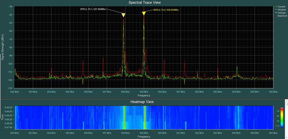
Figure 3
Note also that this is from a unit that has been modified to have separate antenna outputs for Tx-A and Tx-B and that these have, in turn, been put through an antenna combiner (which suppresses some of the IM products). A stock unit would generate much more IM in the high power mode and more than what is shown here in the normal power mode.
Nothing To Gain
The same holds true for antenna gain, which exists solely to overcome signal losses in cables. Using higher gain on an antenna does not help to “pull” Tx signal out of the air. It makes the antenna more sensitive to everything, including off-air DTV and low-level intermod products generated by the normal interaction between wireless transmitters. In other words, it raises the noise floor.
To avoid having to use excess antenna gain, utilize quality cable (this is a whole separate topic), keep cable runs as short as possible, and use a cable loss calculator to determine exactly how much gain is needed and then choose the closest gain setting on the antenna.
In summation:
1) Improper handling and placement of transmitters can generate considerable IM products and raise the overall noise floor. This wastes precious bandwidth.
2) Antenna placement, especially with respect to the orientation of Rx and Tx antennas, is critical for successful outcomes.
3) High Tx power and high Rx gain settings are not helpful unless the specific situation absolutely calls for one or both.
———————————————————
Ike Zimbel has worked in pro audio for 35-plus years, and during that time, he has served as a wireless technician and coordinator, live engineer, studio technician, and audio supervisor for TV broadcasts, and has also managed manufacturing and production companies. He runs Zimbel Audio Productions (zimbelaudio.com) in Toronto, specializing in wireless frequency coordination and equipment repair/modifications.
This article originally appeared on ProSoundWeb.com and is repurposed here with the permission of EH Media.